Monday, April 25, 2016

Cycliq Fly 12 Front Camera + Front Light - First Impressions

After a long wait, the highly anticipated Cycliq Fly 12 is finally here! The Cycliq Fly 12 is a combined front camera plus front light, with some pretty impressive specifications. This follows the successful Cyclic Fly 6 rear camera plus rear light which I also ordered through Kickstarter.

As expected, the Fly 12 arrived later than planned after successfully being funded on Kickstarter. I already knew that this would happen, so I was not too worried that the product was being delayed. It was helped by the fact that I had previously received my Fly 6 successfully, and that there were frequent updates regarding the status of the Fly 12 production samples.

Here is a quick look at the Fly 12!

Unboxing the Cyclic Fly 12!

Key features include Full HD video recording, a powerful front light, long battery life, wireless connectivity, looping recording and rain proof construction.

Detailed specifications of the front camera plus front light

Contents of the box. What stunned me was the "Coming Soon" sticker on the Google Play app, which means that I would not be able to link it to my Android phone yet..

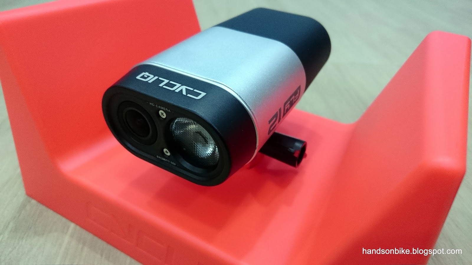
Large camera lens plus large front light dominate the front of the unit

Array of accessories and manual that comes with the Fly 12. Don't think I will need any of them...

Comes with a safety lanyard and a M5 bolt to replace the quick release knob on the GoPro-style mount

The different colours of the indicator light (at top of unit) and what they mean

Incident protection mode to prevent accidental overwriting of critical footage. Same concept as in the Fly 6.


The Fly 12 uses a GoPro type of mount, and is temporarily fixed to the packaging

To remove the Fly 12 from the packaging, first unscrew the bolt holding it from the bottom...

...then twist the whole unit and it detaches from the packaging! Doesn't this look familiar?

Yes, it is the Garmin quarter turn mount! What does this mean?

This means that I can either use the Garmin mount to hold the camera, or use the GoPro mount to fix the camera! The Garmin mounting is actually more convenient as I can quickly remove the camera for charging.

You can use the supplied mount to fix the Fly 12 onto your oversized (31.8mm) handlebar.

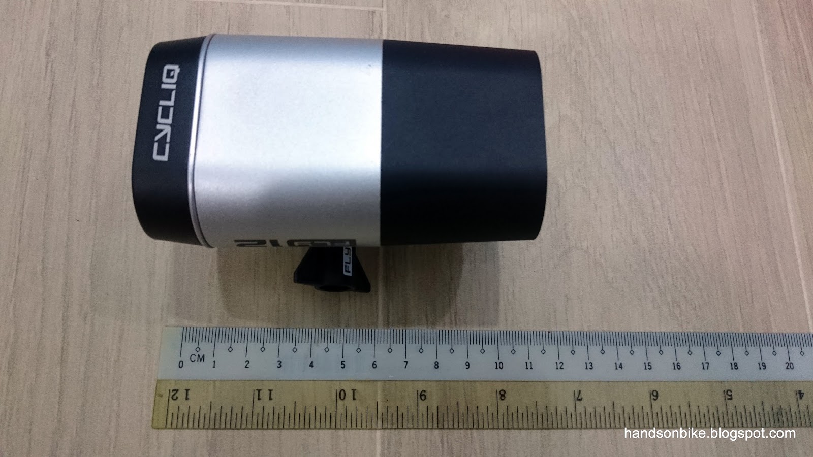
A rough size comparison. Looks quite big as it is one large unit...

Close up look of the front. Full HD camera with 400 lumen front light, very impressive!

Rear of the Fly 12 is where you plug in the Micro USB charging cable or insert the MicroSD card

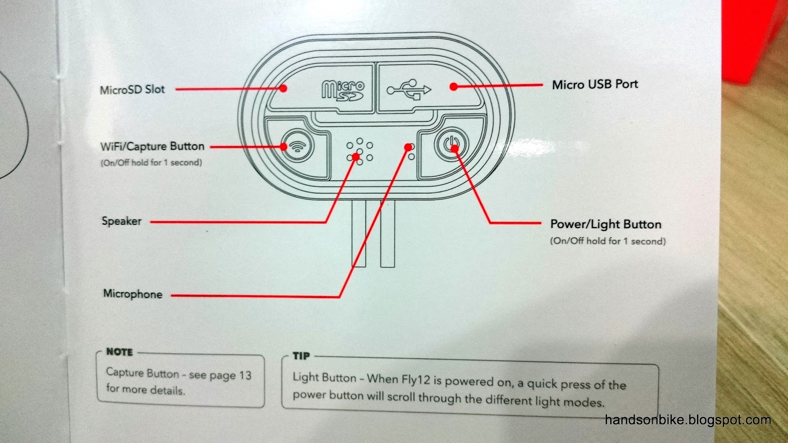
This shows what the two buttons at the rear of the camera does

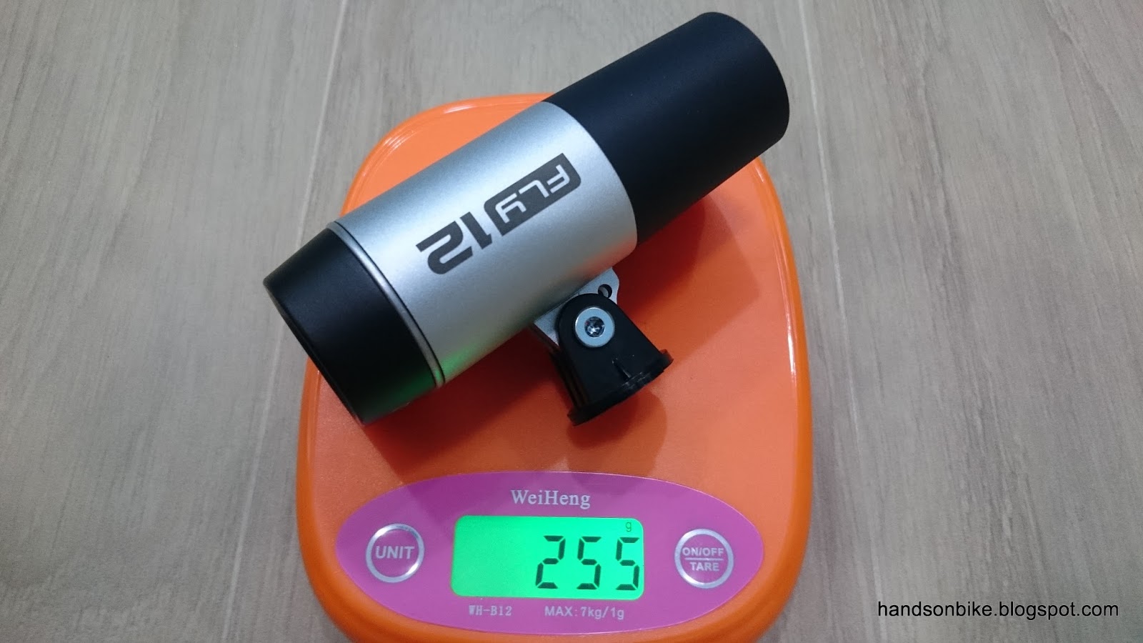
Weight of the Fly 12 without any mounting is 243 grams

I was going to replace the quick release knob on the mount with the M5 bolt, but I found that the M5 bolt does not work! The hexagon shape at the top of the bolt was not formed properly.

I found another suitable M5 bolt and changed the quick release knob to the bolt

Indicator light as shown at the top of the unit

The unboxing of the Fly 12 is complete, and the next step is to install it on the bike and test it out. Since this Fly 12 is quite big, I would prefer not to install it on the road bike as it would look out of place. Instead, I will install it on the Avanti Inc 3 commuting bike, and replace both the Lezyne front light and the Shimano Sport Camera.

To be continued!

Saturday, April 9, 2016

Merida Scultura 5000: Ultegra Di2 6870 Part 1

Back to tinkering around with the Merida Scultura 5000 road bike again! I had recently installed the Ultegra 6800 2x11 mechanical groupset on the Wheelsport Fantasy mini velo, and the Ultegra parts actually came from this Merida bike.

The Ultegra 6870 Di2 components were removed from the Wheelsport Fantasy mini velo, and now it will be installed onto the Merida road bike! The final setup would be Ultegra 6800 mechanical on the mini velo, and Ultegra 6870 Di2 on the road bike.

Prior to this latest upgrade, the Merida road bike was using a mixture of Dura-Ace and Ultegra components. I will be changing the shifting components (shifters, RD, FD) from mechanical to electronic shifting.

Before changing to Di2 components, the road bike is using Ultegra mechanical shifters and Dura-Ace RD and FD

This was the setup not too long ago. Di2 system was on the mini velo, while the mechanical system was on the road bike.

I have already gathered all the required Di2 components, and by now I am familiar with setting up a Di2 bike as I have already done it three times. On the Dahon Boardwalk, the Dahon MuEX, and the Wheelsport Fantasy mini velo. This time, it will be done for the fourth time on the Merida road bike.

Before I can install the Di2 components on the road bike, I have to remove the mechanical components on it. First to go would be the Ultegra 6800 road shifters. These were removed and installed on the Wheelsport Fantasy mini velo.

Ultegra 6800 road shifters removed from the handlebar, leaving the clamp band. Since the clamp band is the same for Ultegra 6800 or 6870 Di2 shifters, I left it on the handlebar as this saves me from unwrapping the whole bar tape to remove the clamp bands.

Next, the frame needs to be prepared for Di2 shifting. I started by identifying the parts that can be removed, as mechanical and electronic shifting has slightly different frame requirements. Before that, I removed the crankset too as this will allow me to access the bottom bracket and also the internal routing that goes past the bottom bracket.

Crankset removed. Notice the red plastic liner that appears under the down tube? This routes the inner cable for the front derailleur.

This stopper is at the head tube side, where the FD inner cable enters the frame and passes through the red liner.

The red liner can be removed as there is no shifter inner cable required for Di2 shifting.

One reason why I like threaded BB: It can be removed easily for servicing. This black piece of plastic is the cable guide for the FD inner cable, which can also be removed as it is not required.

The Ultegra 6870 Di2 components taken off from the Wheelsport mini velo, and now ready to install onto the Merida road bike!

The battery mount on the Wheelsport mini velo was using the long battery mount, but I changed it back to the previous short battery mount to use on the Merida road bike

Before I started this project to install Ultegra Di2 on the Merida road bike, I have already noticed that this frame is designed to allow Di2 internal wire routing. There are multiple holes on the frame to allow Di2 wires to be routed internally. Examples will be shown below.

The battery mount can be installed under the left chainstay, using the designated battery mount as shown by the two bolts here. The hole on the frame is for the Di2 wire to go into the frame.

Battery mount installed! Located unobtrusively under the left chainstay

Ultegra 6870 Di2 Rear Derailleur installed. The Di2 wire is routed through the right chainstay.

Ultegra 6870 Di2 Front Derailleur installed. The hole under the FD mount is for the Di2 wire to go into the frame.

As with most frame designs, the Junction B of the Di2 system will be located somewhere around the bottom bracket area. Therefore, all the 4 wires (from RD, FD, battery and Junction A) will meet Junction B at the bottom bracket area. Before connecting up all the components, I will run all the wires from the individual components to the bottom bracket area.

Di2 system layout will be the same as on the Wheelsport Fantasy mini velo, but with different lengths of wire between components due to the different frame geometry.

The right side hole on the frame will be closed off as it is no longer required.

On the left side, the Di2 wire that joins Junction A to Junction B will pass through the frame. However, the connector head is too big to fit through the original rubber grommet.

I made my own DIY rubber grommet using the rubber bellow from a V brake. This plugs into the hole on the frame and guides the Di2 wire through the frame along the downtube.

Di2 wire from the FD passes through the hole on the seat tube and downwards to the bottom bracket area

The D-Fly wireless unit is connected between the RD and Junction B. It will be mounted on the right side seatstay as recommended.

Finally, the Di2 wire from the battery will enter the frame from the hole at the bottom.

Now that all the wires have been routed from the components to the bottom bracket area, the next step is to join them to Junction B. This is not that easy as there is very limited space around the bottom bracket to connect and secure Junction B internally. To be continued!

Click here for Part 2!